Question 1.b
Do you believe there is any premium that you could identify as part of the leaning columns or canted walls on the office building?
Leaning Columns and Canted Walls
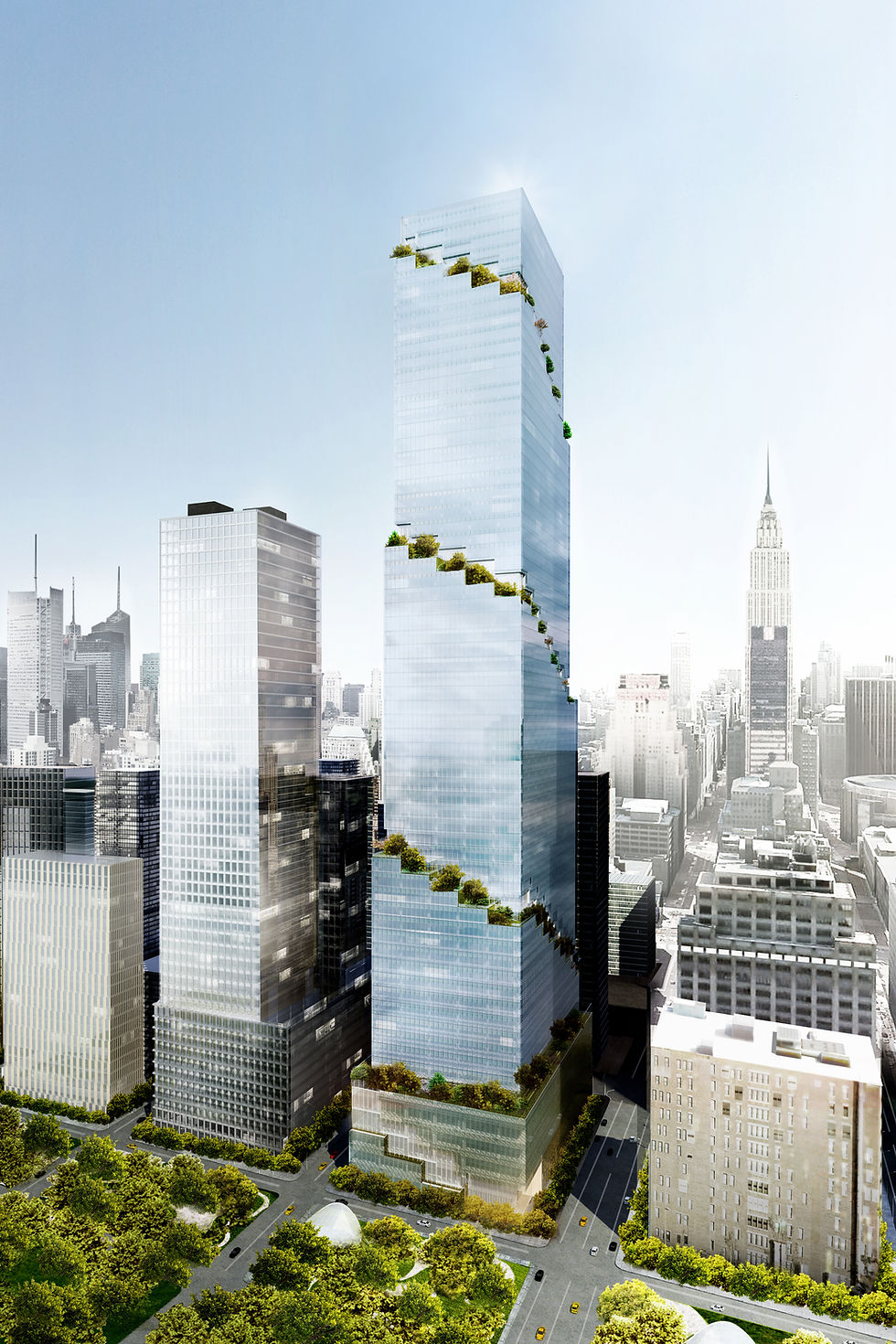
The RFP queries asked for potential premiums associated with structure of the commercial tower, in particular, the slanted columns and canted walls. There are some particular challenges associated with the construction of these items and also with the leaning of the tower and shifting of the floor plates.
Generally, these elements alone do not require significant amount of added materials but do require specific planning in terms of design and construction sequence and, if not addressed properly, can lead to serviceability issues and sometimes retrofitting. Thus, while nominal added materials and direct costs are expected, the costs associated with the design, planning and sometimes monitoring can be significantly more.
The design challenges for the structure manifest themselves in keeping the form of the architecture, while avoiding discontinuities in the structure leading to serviceability issues, e.g., nodal connections, diaphragm forces in the slab plane, transfer beams, etc.
The construction challenges occur in constructing a non-orthogonal structure, built not to the theoretical locations, but in manner so as to preempt or compensate for the building movements during and after construction.
These challenges are summarized in the following table:
Shifting Floor Plates
The tower floor plates shift at each floor and each floor shape is unique and asymmetrical. Additionally, balconies and double height spaces Other than dictating the column locations around a slab edge that changes floor-by-floor, the primary challenge of this, whether structural steel or PT concrete, is in the erection of the customized edge elements (formwork or steel and metal decking). Materially, this may not be significant, but will be more labor and time intense than with repetitive floors. The crews will not be able to get into a repetitive cycle and this will add to floor-to-floor cycle time, likely by an additional day per floor, when compared to an orthogonal, repetitive floor structure.
Sloped Columns
Sloped columns, in both concrete and steel, present unique challenges and potential engineering and cost premiums. The current structural design (excluding proposed alternatives) includes structural steel framing with metal decking and lightweight concrete starting at the amenities floor on L12. Below this is wide post-tensioned (PT) band-beams with one-way spanning slabs between the beams.
The more significant shift in floor plates and lean of the tower also begins at L12 continuing to the roof. This configuration, with the lighter steel framing, supported by steel columns that will not creep (deform with time), is ideal.
The concept narrative included an option to use similar PT band-beam framing from the lower tower in lieu of the steel framing above. See extract below.
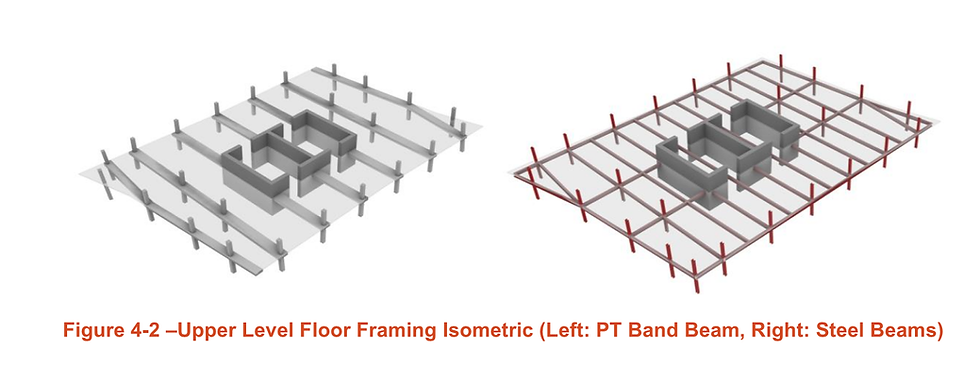
Figure 2 Extract from Thornton Tomasetti Design Narrative - Concrete Framing Option.
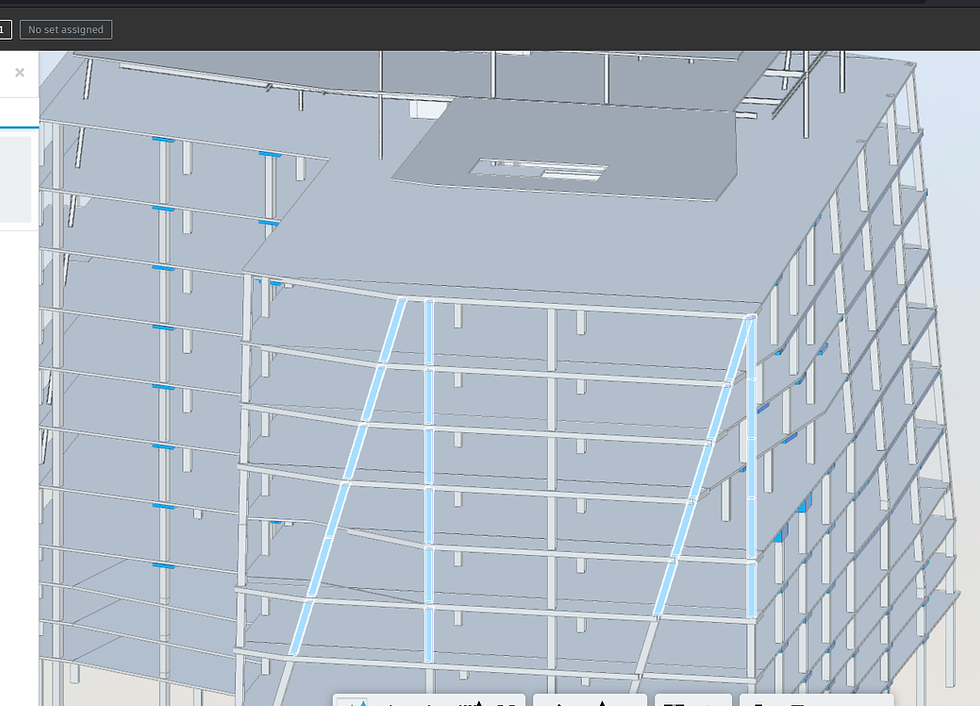
Figure 3 Sloped Columns (Not to Work Points)
Changing to a PT band beam scheme for the upper floors would increase the floor loading on these floor, and rely upon concrete columns that would be subject to creep (long-term deformation) considerations. Therefore, exploring this alternative is not recommended.
Overall, the challenges with the sloped columns can be summarized as follows:
-
Fabrication: depending on the slope they are considering and use of a two floor (tier) or single floor column; the column sizing and connection details may have a minor fabrication and cost impacts
-
Depending on loads, if the splice connection becomes large and nodes are required and/or splice connections increase substantially for erection purposes.
-
A slight increase in materials and cost is expected for eccentric loads / moments to other members.
-
Additional welding requirements will be expected in the field.
-
-
Spandrel beams are likely to be increased in size due to loads from the curtain wall.
-
Erection: erection sequence, unless splice connection is detailed to hold columns in place until framing beams are connected, or temporary cabling/guying may be required.
-
Once engineered study is done for building movement, column shortening, deflections, etc. there could be additional concerns for tolerances that need to be built in.
-
The requirements are more substantial for the concrete columns and braces than the steel elements.
-
-
Other trades: window washing requirement, depending on what system (rig) is designed, would be an up charge from simple davit system; along with ww ties/ track to CW
-
Curtainwall – installation premium of unitized panels on slope, in particular if panels stay at 10’ (outrigger and install )--- clip assembly tolerances to incorporate deflection requirement
We note that some of the diagonal columns do not intersect / connect to work points (concentric centers). The connections of these elements will need to be developed in detail for force resolution, constructability and to avoid serviceability issues.
A wellpoint system is similar to an educator system in that it operates by vacuum extraction of groundwater and consists of closely-spaced small diameter wells. However, a wellpoint system only requires vacuum lines from a vacuum manifold (rather than both supply and return manifolds of an educator system). The wellpoints have a limitation of pumping head such that it is not generally practical at a depth of greater than about 15 feet. Therefore, the wellpoint system could be installed on the interior of the excavation after the excavation has advanced to within proximity of the groundwater. Then the wellpoint system can be installed from the interior of the excavation, through the shoring, between soldier beams, with the vacuum manifold hung from the shoring. This is illustrated in Figure G3 and is shown in cross-section in Figure G4.
Transfer Beams for Stepping Columns
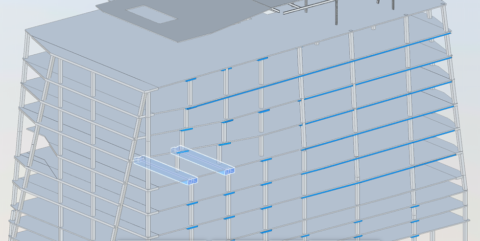
Figure 4 Transfer Beams in Model (Highlighted)
Overall, the constructability of the structural elements (and the need to consider testing and monitoring) will be determined as the structural design develops. Turner looks forward to working with the design team to ensure timely and efficient delivery of the project, utilizing our vast resources and calling upon our experience with various similar projects.
Conclusion
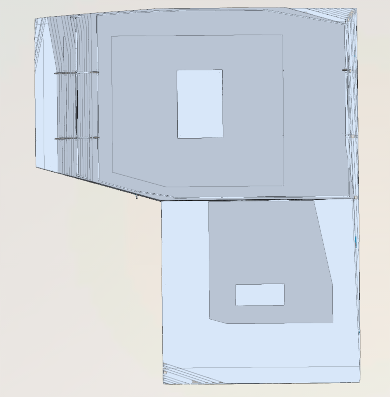
Figure 1 Overall Plan Showing the Shifting Slab Edges.
Experience with Leaning Buildings, Sloping and Stepping Columns
Bitexco Financial Tower, Vietnam
Similar to the Greyhound Commercial tower, the 262m (860 ft.) 68-story, Bitexco Financial Tower (BFT) has asymmetric floor plates that shift at each floor, with inclined columns that follow the shifting slab edges, at every floor. The tower shape led to an eccentric loading under gravity; i.e., the tower would lean under gravity loading unless constructed with pre-emptive corrections in the columns (otherwise sloping floor plates would occur).
Additionally, since the tower was constructed in reinforced concrete, and concrete under sustained loading experiences deformation in the form of creep, the long-term effects for the concrete had to also be considered, not just the "as constructed" state of the building. To plan for this, a specialist engineer and monitoring contractor was engaged to determine the actual concrete mix properties for long-term stiffness (modulus of elasticity) along with an iterative monitoring plan to counteract these effects.
The information obtained from long-term stiffness testing and installed monitoring was used to forecast the corrections (vertical cambering) in the tower columns and this was updated and iterated throughout the tower construction. In the end, some of the columns were compensated (increased in length) up to 80mm (3-in.).
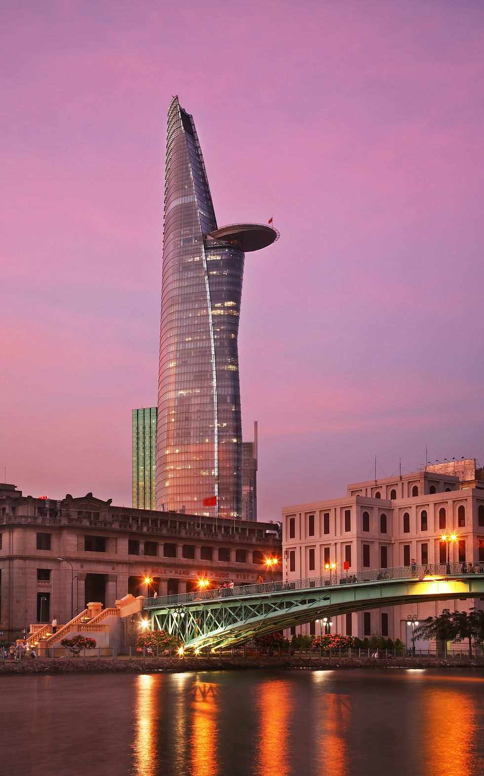
Figure 5 BFT Long-Term Concrete Testing for Creep and Shrinkage, Concrete Sensor Instrumentation, Predicted Column Deformations vs. Actual Deformations, and Column Compensation Diagram Extract.
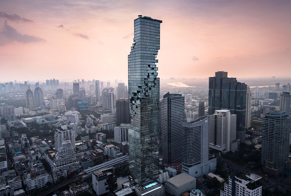
Mahanakhon Tower, Thailand
The 314m (1030 ft.), 77-story, MahaNakhon Tower, with its stepped core and stepping perimeter columns achieved the architectural intent and the pixelated façade; however, this created an eccentric loading condition under in the tower’s as constructed state, i.e., the tower would lean once built without preemptive compensation in the tower construction. Therefore, the tower was built approximately 16‑inches out of plum, so that in its final state it would be vertical.
Merdeka 118, Malaysia
Currently completing construction with 118 occupied floors and soaring 680m (2,230 ft.) Merdeka 118 is now the second tallest building in the world (following Burj Khalifa, also a Turner project).
Similar to the Bitexco Financial Tower, Merdeka 118 performed long-term concrete testing, but for period of three-years starting before the superstructure construction and continuing through the superstructure construction. This led to a compensation strategy for the columns averaging approximately 3mm / floor (1/8” / floor) for a total column compensation of approx. 400mm (16-in.) at the top of the tower. The tower is comprised of inclined composite mega-columns along its perimeter to develop its faceted façade and considering the project scale and interconnection of the mega-columns to various outrigger levels necessitated the need for advanced concrete monitoring.

Figure 6 Merdeka Multiyear Strain Readings.